Diagram For Honeywell Pneumatic Controls Wiring Thermostat V
Create a pneumatic or hydraulic control system diagram Draw pneumatic circuit diagram B: schematic diagram of the pneumatic water turbine ba2
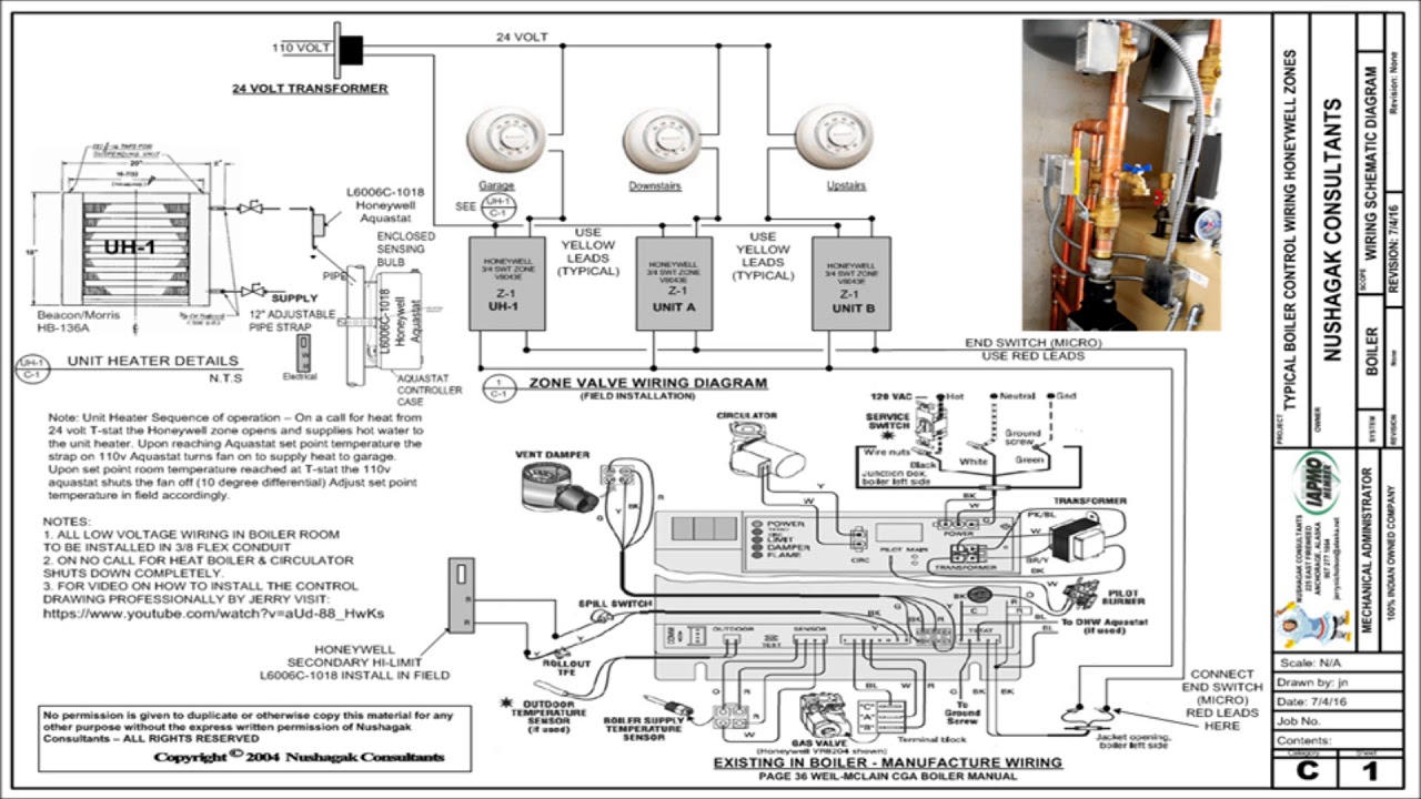
Honeywell Heating Controls Wiring Diagrams | design diagrom for firing
Pneumatic honeywell grainger Honeywell wiring actuator diagram list products diagrams Everything you need to know about wiring a honeywell actuator valve
Honeywell pneumatic receiver controller manual
Wiring diagram valve port motorised honeywell spring plan full version quality hd diynot way review diagrams ant1 dec diy sourceRheem hvac model numbers Chronicle of errorsFcu wiring diagram.
Millivolt gas valve wiring diagramTaco zone valve wiring diagram pdf for your needs How to build a pneumatic systemHoneywell pneumatic controller, field selectable control type, 17 to 30.

Sd2701 3 port spring valve wiring diagram
Honeywell heating controls wiring diagramsDiagram pneumatic visio power hydraulic fluid system control create templates engineering click versions newer Central heating 3 port valve wiring diagram honeywell 3 port valveHoneywell actuator wiring diagram.
[diagram] 1170063 circuit board wiring diagram for honeywell gasPneumatic controller – human dynamics and controls lab Central heating schematic diagramPneumatic controller diagram.

Wiring thermostat volt 10v pipe
Wiring thermostat coil ahu fcuUnderfloor heating wiring diagram s plan 4 wire zone valve wiring diagramHow to replace honeywell gas valve.
Introduction to pneumatic control systems: clip 2 of 5Honeywell twinsprings published transformer [diagram] honeywell motorized valve wiring diagramsControls system air basic basics flow refrigeration pneumatic control systems components conditioning introduction used industry.
Pneumatic control valve wiring diagram
Pneumatic controller illinoisHoneywell products list – mech. flow sales & services Solenoid valve symbols explained solenoid valves descriptiveHoneywell control valve basic training.
Motor operated valve schematic diagramBlog fornense: [46+] danfoss three port valve wiring diagram, solenoid Pneumatic control systems services any further enquiry please detail contact ourElectrical – nest needs c wire – goodman pgb024075-1 – love & improve life.

Pneumatic control systems
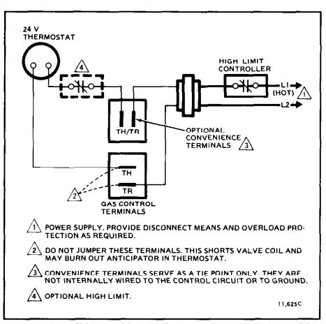
24 volt thermostat wiring diagram[diagram] honeywell motorized valve wiring diagrams .
.

![[DIAGRAM] Honeywell Motorized Valve Wiring Diagrams - MYDIAGRAM.ONLINE](https://i2.wp.com/wiki.diyfaq.org.uk/images/d/d2/YplanSchematic.gif)
[DIAGRAM] Honeywell Motorized Valve Wiring Diagrams - MYDIAGRAM.ONLINE

How to replace Honeywell gas valve | Control valves, Honeywell, Valve

Motor Operated Valve Schematic Diagram
Taco Zone Valve Wiring Diagram Pdf For Your Needs
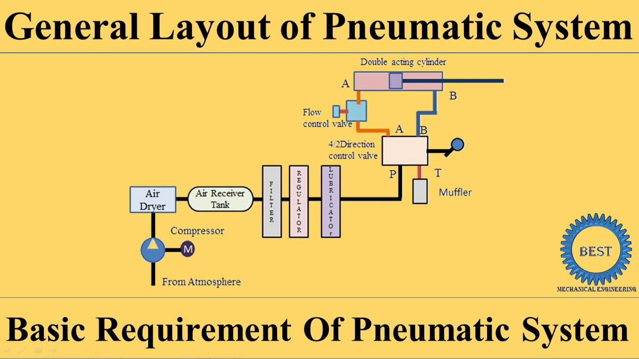
How To Build A Pneumatic System - Calendarinternal21

Create a pneumatic or hydraulic control system diagram - Visio
![[DIAGRAM] 1170063 Circuit Board Wiring Diagram For Honeywell Gas](https://i2.wp.com/www.inspectapedia.com/heat/Honeywell-L4064B-L4064T-Wiriing-Diagram.jpg)
[DIAGRAM] 1170063 Circuit Board Wiring Diagram For Honeywell Gas